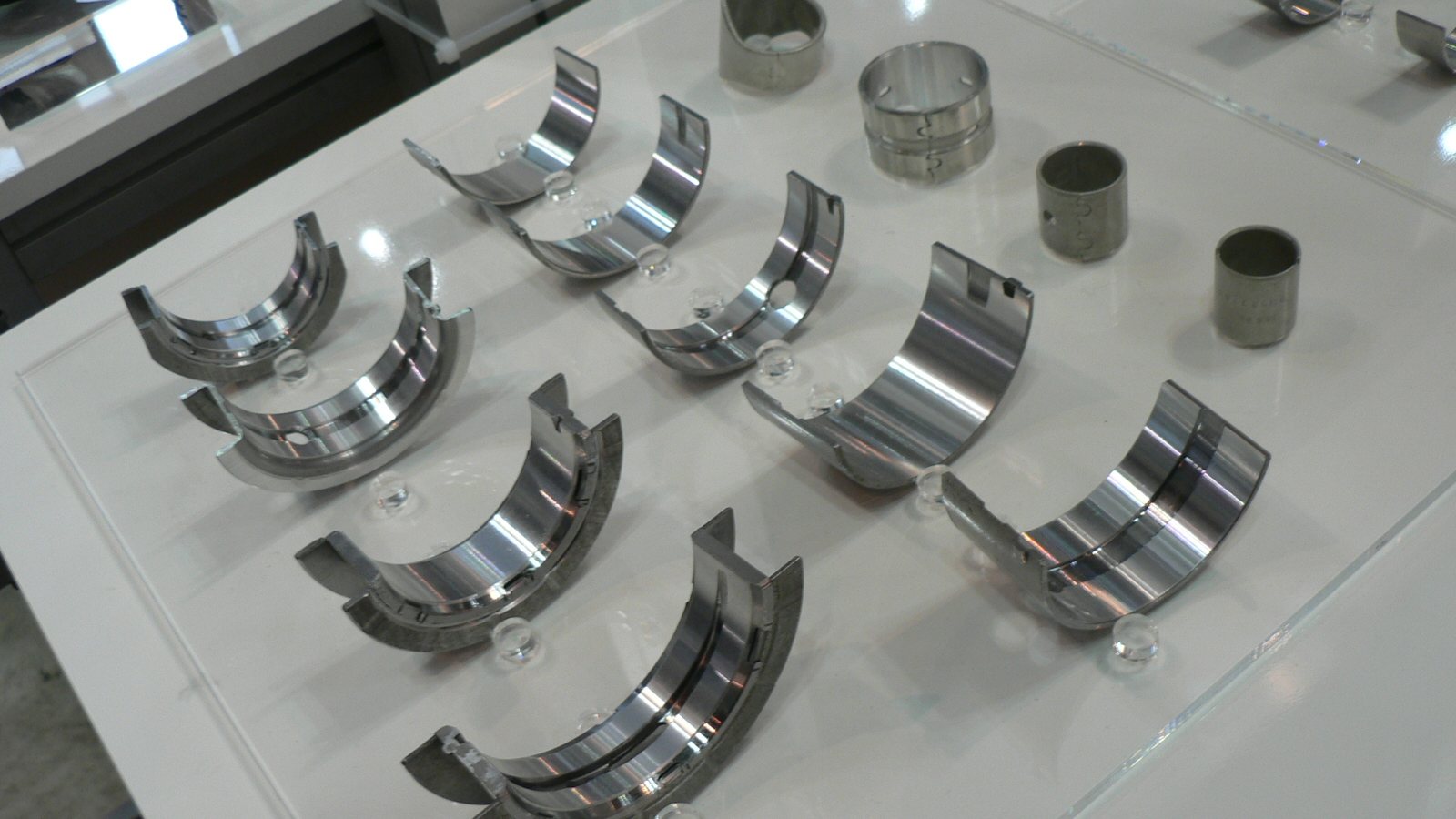
Engine bearings are among the most critical components in any marine diesel engine. Main bearings support the crankshaft, while connecting rod (big-end) bearings transfer the force from the pistons to the crankshaft. Bearing failure can result in catastrophic engine damage, making timely inspection and replacement essential for reliable marine operations.
Marine diesel engines use hydrodynamic plain bearings (also called shell bearings or journal bearings) rather than rolling element bearings. These consist of two half-shells lined with soft bearing material that forms an oil film between the bearing surface and the crankshaft journal.
**Main bearings** are located in the engine block and support the crankshaft at each journal position plus a thrust bearing that controls crankshaft axial movement.
**Connecting rod bearings** (big-end bearings) connect the piston's connecting rod to the crankshaft crankpin, converting reciprocating motion into rotary motion.
**Bearing materials:**
Bimetal (steel + aluminium-tin alloy) — Common in medium and high-speed engines (CAT, Cummins, Volvo Penta)Trimetal (steel + copper-lead + tin overlay) — Used in medium-speed engines (Wärtsilä, MaK) for higher load capacityWhite metal (Babbitt) — Traditional material for large low-speed engines (Sulzer, MAN B&W)Bearing replacement should be based on condition monitoring, not just running hours:
**Oil analysis indicators:**
Rising copper content (>30 ppm) — overlay wearing throughRising lead content (>20 ppm) — bearing material exposedRising tin content — advanced bearing wearIron particles — journal or bearing back wear**Physical inspection indicators:**
Bearing clearance exceeds manufacturer maximum (measured with Plastigauge or feeler gauge)Visible scoring, pitting, or fatigue cracking on bearing surfaceOverlay worn through to copper-lead intermediate layerFretting or movement marks on bearing backsCrankshaft journal wear or ovality exceeding limits**Typical replacement intervals:**
High-speed engines (Volvo Penta, Scania): 12,000–20,000 hoursMedium-speed engines (Wärtsilä 32, MaK M32): 24,000–48,000 hoursLow-speed engines (Sulzer RTA): 40,000–80,000 hoursCorrect bearing clearance is critical — too tight causes overheating and seizure, too loose causes hammering and oil film breakdown.
**Methods:**
Plastigauge — A calibrated plastic strip placed between the bearing and journal. After torquing the cap, the crushed width indicates clearance. Quick and accurate for in-situ checks.Feeler gauge — For checking clearance with the crankshaft lifted by hydraulic jack (large engines).Bridge gauge and inside micrometer — Most accurate method: measure bearing bore with cap torqued, then measure crankshaft journal with micrometer. Calculate clearance by subtraction.**Typical clearances (guide only — always refer to manufacturer specifications):**
Main bearings: 0.08–0.15 mm (medium-speed engines)Connecting rod bearings: 0.06–0.12 mm (medium-speed engines)Thrust bearing axial clearance: 0.15–0.40 mm**Preparation:**
Drain engine oil and tag all bearing positionsRemove sump/crankcase covers for accessMeasure existing clearances before disassembly (for baseline)Turn crankshaft to access each bearing position**Main bearing replacement:**
Remove main bearing cap bolts (note: stretch bolts must always be replaced)Remove lower bearing shell from capUse a bearing roll-out tool or turn crankshaft to extract upper shellInspect crankshaft journal — measure diameter in two planes at 90° and check for ovalityClean journal and bearing housing thoroughlyInstall new upper shell (align locating tab with slot)Install new lower shell in capLubricate bearing surface with clean engine oilTorque cap bolts to specification in correct sequenceCheck clearance with PlastigaugeVerify crankshaft turns freely**Connecting rod bearing replacement:**
Remove cylinder head and piston/liner assembly (or use piston-up method for some engines)Remove connecting rod cap boltsRemove lower shell and inspect crankpin journalInstall new shells with correct orientationTorque cap bolts to specificationCheck clearance and crankshaft rotation**Wärtsilä W32:**
Main bearing: trimetal, interference fit 0.02–0.04 mmConnecting rod bearing: trimetal, clearance 0.08–0.14 mmThrust bearing: steel-backed white metal padsCap bolt torque: as per engine-specific manual (hydraulic tensioning)**Caterpillar 3500 Series:**
Main bearing: bimetal aluminium-tin alloyConnecting rod bearing: bimetal with polymer coatingMain bearing clearance: 0.076–0.178 mmRod bearing clearance: 0.064–0.152 mmCap bolt torque: 475 Nm ± 35 Nm (3512)**Cummins KTA38/KTA50:**
Main bearing: trimetal copper-lead-tinConnecting rod bearing: trimetal copper-lead-tinMain bearing clearance: 0.076–0.178 mmRod bearing clearance: 0.076–0.152 mmAlways replace stretch boltsOil starvation — Blocked oil galleries, low oil level, or pump failure. The most common cause of catastrophic bearing failure.Contaminated oil — Water, fuel dilution, or dirt particles damage the bearing surface. Maintain oil filtration and analysis programme.Misalignment — Crankshaft deflection from hull stress, engine mount deterioration, or improper installation causes uneven bearing loading.Overloading — Sustained operation above rated power accelerates bearing wear.Incorrect clearance — Wrong bearing size or improper installation.Material fatigue — Normal wear mechanism — overlay cracks and flakes after extended service life.## How MarineLink Solutions Can Help
We supply genuine and OEM-quality main bearing shells, connecting rod bearing shells, thrust bearings, and crankshaft seals for all major marine engine brands. Our technical team can cross-reference part numbers and advise on correct bearing selection for your specific engine serial number.
Contact us at sales@marinelinksolutions.com or WhatsApp +353 86 102 0717 for competitive quotes with fast worldwide delivery.